Snap Circuits Lift-Off!
Adding a “brain” to the classic Snap Circuits
Note: This project requires an Elenco Snap Circuits kit that includes the fan blade.
How it Works
After pressing the up button on the BrainPad, the motor starts spinning and turns the fan blade (propeller). The BrainPad display starts counting down and at the end of the countdown the motor stops which releases the fan blade launching it into the air.
Snap Circuits Set Up
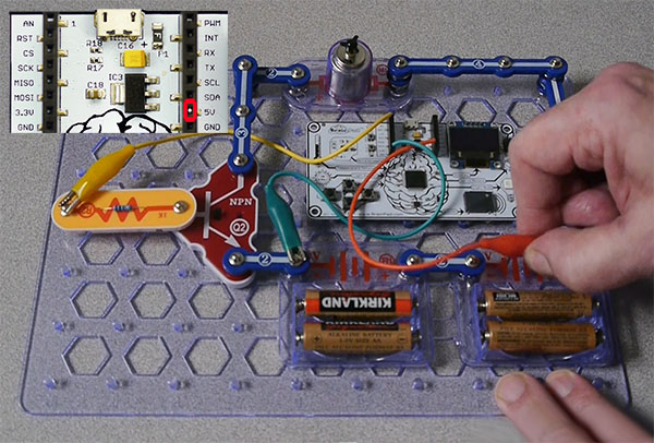
Follow the diagram below and the step-by-step guide to build the circuit!
The Hardware
Duration: ~20 minutes
Materials
- Elenco Snap Circuits Kit (we used Model: SC300)
- BrainPad (www.brainpad.com)
- 3 – 6 inch Wires with Aligator Clips
Assembly
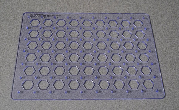
Step 1: Base Grid
First, place the Base Grid (#6SCBG) onto a flat surface. We will connect all the components to this base.
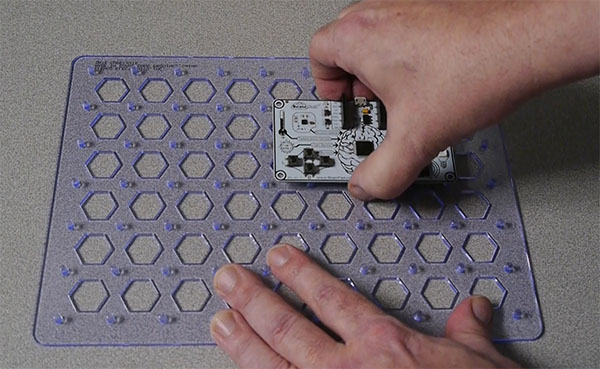
Step 2: Mount the BrainPad to the Base Grid
Next, we will mount the BrainPad to our Base Grid. Place the BrainPad on the 2nd Row at the 5th Hexagon, as pictured.
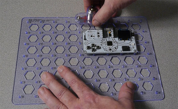
Step 3: Add the Motor for our Fan
Find the M1 Motor Module (#6SCM1). Attach the module to the Base Grid on the 5th snap at the top of the grid, as pictured.
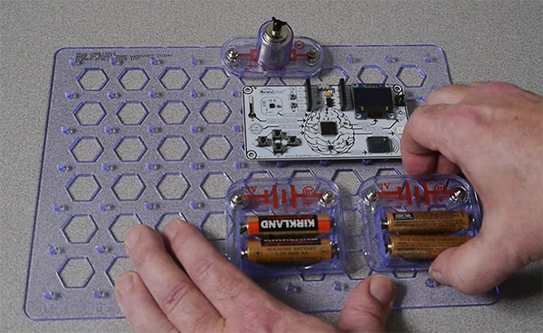
Step 4: Add the battery holder
Next, we’ll add a Battery Holder – B1 (#6SCL1) to power our the BrainPad and our Snap Circuit. Place the first Battery Module on the 5th row/5th column of the Base Grid.
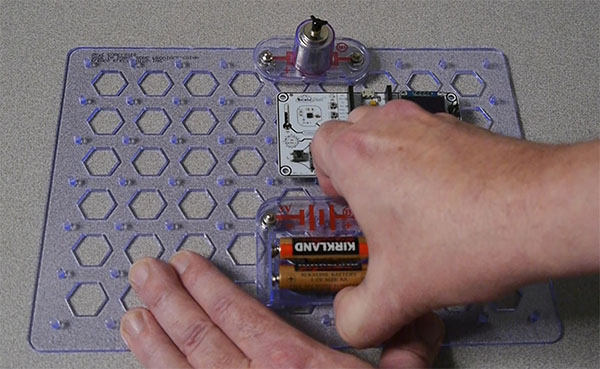
Step 5: Connect a 2nd battery holder
Snap-in the 2nd battery pack on the same 5th Row next to the other battery pack on the 8th column, as pictured.
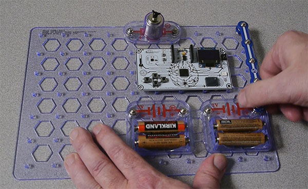
Step 6: Connect 5-Snap Wire
Now we will connect our first 5-Snap Wire (#6SC05) labeled ‘5’ to our circuit. We will also need a 1-Snap Wire (#6SC01) spacer labeled ‘1’. Snap-in the spacer at the top right corner of the Base Grid. Next, connect the 5-Snap Wire to the spacer and the top left snap of our 2nd Battery holder as shown in the picture.
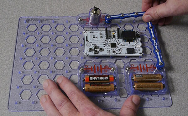
Step 7: Connect a 4-Snap Wire
Next, we will connect a 4-Snap Wire (#6SC04) labeled ‘4’ to our circuit. First place another 1-Snap spacer on the right side of our Motor module – M1. Next, snap the 4-Snap Wire onto the spacer we just added to the M1 module. Connect the other end to the 5-Snap Wire we placed in the previous step. Connecting the two Snap Wires together.
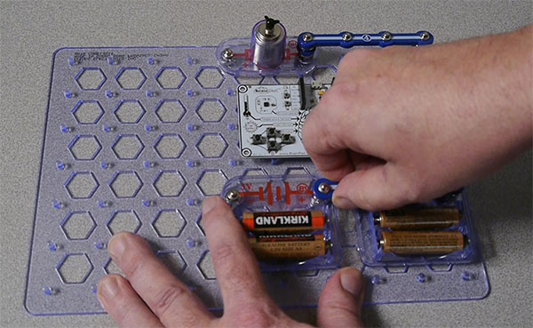
Step 8: Connect Battery Holders
Now we will use a 2-Snap Wire (#6SC02) labeled ‘2’ and connect both Battery Holders together as shown below.
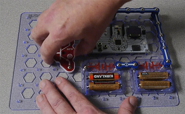
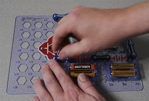
Step 9: Connect a Transistor
Next, we will place the NPN Transistor Q2 (#6SCQ2) We can place it in the 4th row and 3rd column. Place in the direction shown in the image below. The Transistor is used to amplify the signal from the Brainpad.
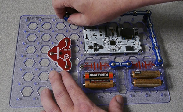
Step 10: Connect 2-Snap Wire
Snap-in a 2-Snap Wire (#6SC02) labeled ‘2’ to left side of the ‘M1’ Motor Module. Also, add a 1-Snap spacer to the bottom of the 2-Snap Wire. As shown below. We will leave the other end unconnected for the moment.
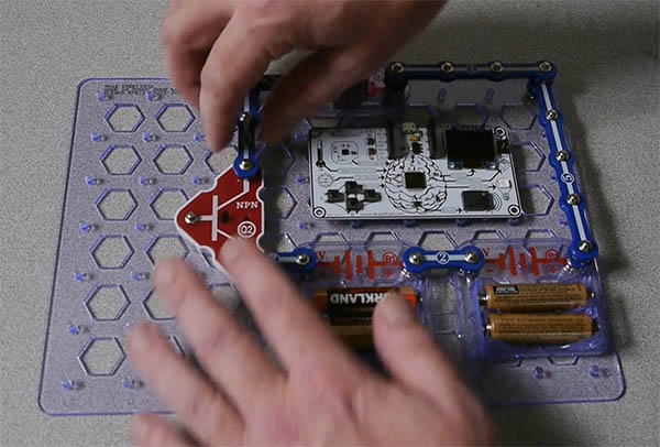
Step 11: Connect 3-Snap Wire
Next, we will connect a 3-Snap Wire (#6SC03) labeled ‘3’ to the 2-Snap Wire we just placed, then connect a 1-Snap spacer to the other end of the 3-Snap Wire. Connect it to the top of the Transistor Module ‘Q2’.
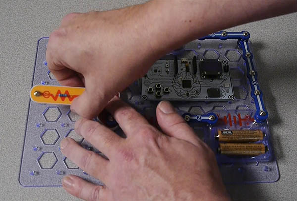
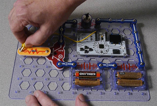
Step 12: Connect the Resistor Module
Connect the Resistor Module (#6SCR1) labeled ‘R1’ to the far left snap on our Transistor Module ‘Q2’. As demonstrated in the image below.
Step 13: Connect 2-Snap Wire
Connect a 2-Snap Wire (#6SC02) labeled ‘2’ to the bottom snap on our Transistor Module ‘Q2’. As demonstrated in the image below. Connect the other end to the nearby battery module.
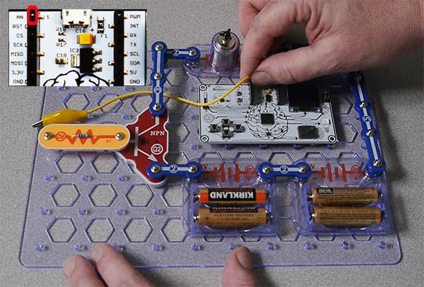
Step 14: Connect a wire to the BrainPad Expansion Header
Find a wire with an Aligator clip on one side and bare wire on the other end. Connect the bare wire end into the ‘AN’ pin of the left side of the BrainPad’s expansion header.
Step 15: Connect the Wire to Resistor
Connect the Aligator clip end of our wire to the end of the ‘R2’ Resistor modules, as shown below.
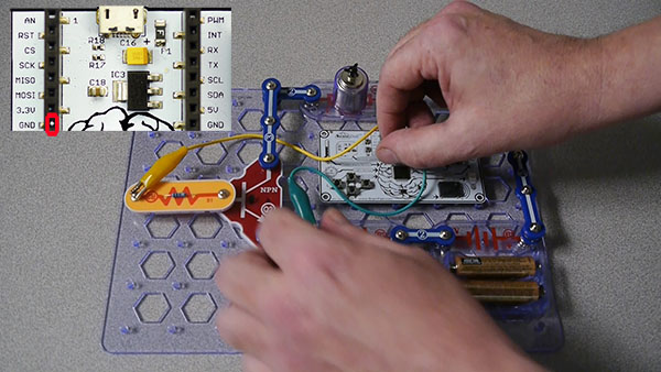
Step 16: Connect Ground Wire to 2-Snap Wire
Connect the 2nd Aligator clipped bare wire to Ground (GND) pin on the left BrainPad’s expansion header. Then connect to the 2-Snap Wire that is connected at the bottom of the NPN Transistor module ‘Q2’, the 2-Snap Wire, that is connected to the left battery module.
Step 17: Connect a wire from the BrainPad Expansion Header
Connect our 3rd Aligator clipped bare wire to the 5V pin on the right side of the BrainPad’s expansion slot, connect the clip end to the far-right Snap on the right battery module.
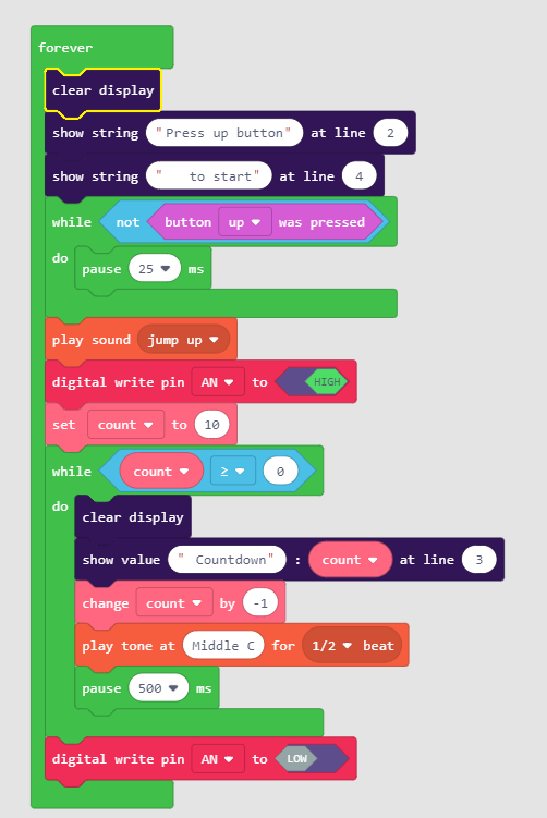
The Code:
In the code below, the program waits for a user to click the button, when they click the button, a sound will play, they will set the AN pin to HIGH which will start the motor, and then begin the countdown from 10. After 10 seconds, the pin will turn LOW and the fan will liftoff. Turning the motor on for a few seconds then turning it off is what makes the fan take off. If it stays on, you are either not letting it spin up long enough, or you have it wired wrong and it is blowing air like a fan.