BrainSense Intro
This lesson is an intro to circuits and physical computing, the BrainSense kit makes for exploring smart homes by simulating their functionality through the integration of motors and sensor modules, facilitated by an I/O expansion board shield.
Prerequisite
You must have completed some basic coding lessons and understand coding concepts like variables and loops. You can use any of the supported languages on the Coding Lessons page.
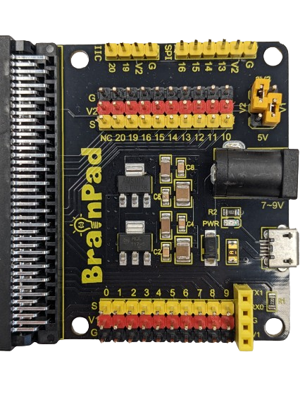
I/O Expansion Board Shield
IO (Input/Output) expandability refers to the ability of a device to increase the number and types of connections it can support for input and output. In simpler terms, it’s the capability to add more ways for a microcomputer to receive or send information.
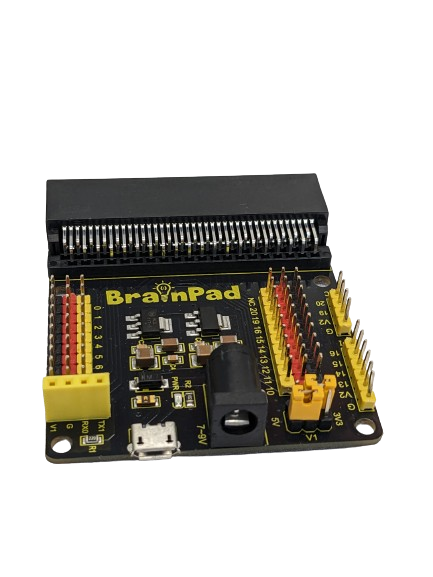
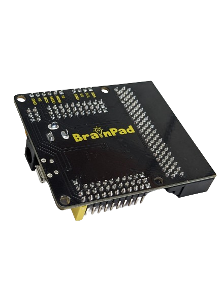
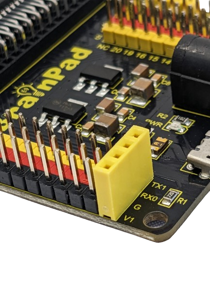
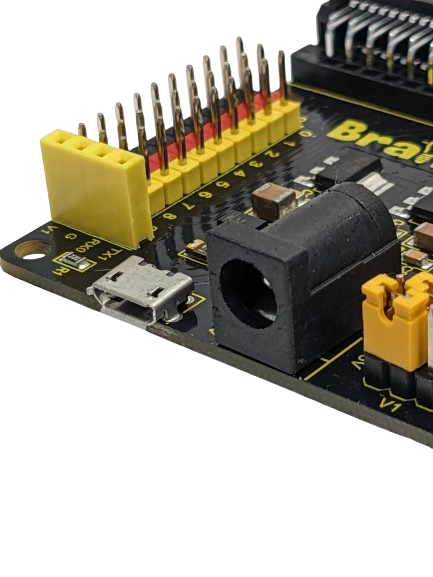
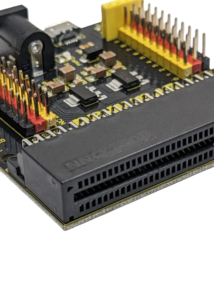
The BrainPad Expansion Board simplifies testing with motors and sensor modules by breaking out control ports into 3PIN interfaces. It extends serial communication interfaces, like I2C and SPI, for seamless connection between the control board and other devices. The shield offers power flexibility with options for voltage selection (V1: PIN 0 to PIN 9 | V2: PIN 10 to PIN 20). Both V1 and V2 provide 3.3V or 5V according to the jumpers in the voltage selectable section, the board is also can be powered via a DC jack (DC 7-9V) or a micro USB port (DC 5V).

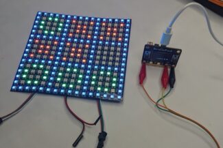
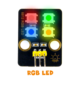
The Modules
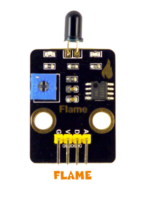
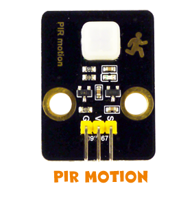
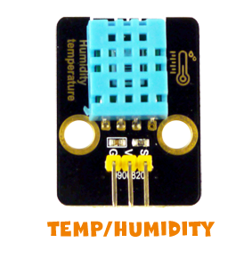
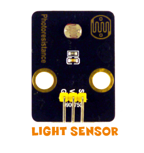
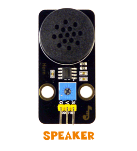
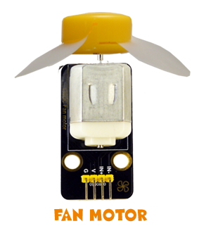
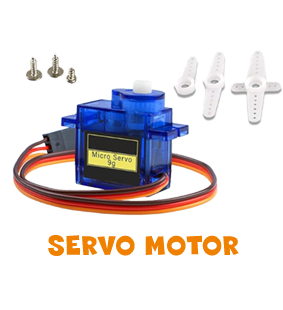
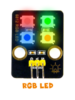
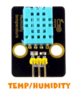
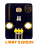
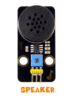
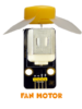
The included modules have many sensors and elements that cover a lot of topics.
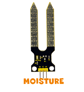
It is also possible to connect other sensors. There are hundreds of electronic modules found online, like a gas sensor or a relay for example. Those sensors typically have pins for wiring.
Making Connections
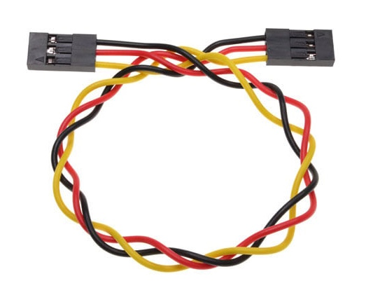
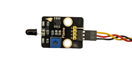
The wiring employed with the I/O board and the modules is highly common, it’s female headers at both ends.
The wires are commonly supplied as a set of three integrated cables with different colors: black for GND, red for VCC, and yellow for the signal.
The signal pin on each module will need to connect to one of the I/O Board Shield yellow pins. These signal pins can be digital or analog and do things specific to the module being used.
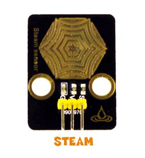
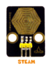
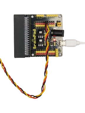
For instance, here the Steam sensor is connected to PIN 5 by linking GND, VCC (5V), and signal wire. This configuration is enabled by the jumper in the voltage-selectable section, bridging between V1 and 5V, as well as between V2 and 3.3V.
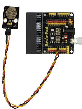
In contrast, when aiming to connect the sensor to VCC at 3.3V, simply adjust the jumper placement to bridge between V1 and 3.3V.
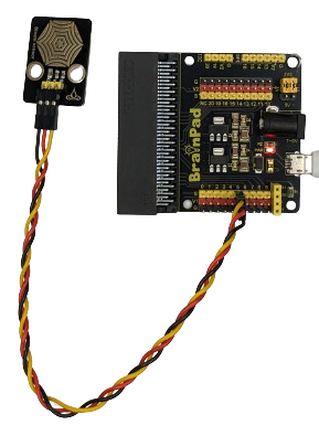
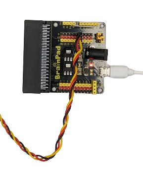
Similarly, the process applies to V2: to connect the sensor to PIN 14 with 3.3V (V2), position the jumper as shown in the right photo; alternatively, for a connection with 5V, configure the jumper placement as shown in the left photo.
For modules featuring 4 pins—VCC, GND, and two others labeled A (Analog) and D (Digital)—the connection is established by wiring in alignment with VCC, GND, and the Digital pin.
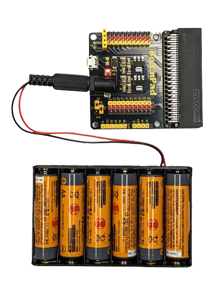
Battery Holder
The battery holder has six AA batteries, providing approximately 9V output, Also, It has a power jack wire for convenient connection to the IO Expansion board shield.
What’s Next?
Start learning about digital and analog controlling. Depending on the language of choice, see the Coding Lessons page.
BrainStorm
The BrainSense kit is designed as a smart home prototype, having a set of sensors helps us not only to reduce power consumption and environmental impact but also to introduce automated functionalities for a more convenient lifestyle. To enhance the smart capabilities further, contemplate the incorporation of additional sensors or modules not present in the existing kit.
Explore the possibilities offered by the BrainTronics kit, which has a collection of sensors and modules that seamlessly integrate with the BrainSense system. This exploration opens the door to expanding the intelligence of various aspects within our homes.